» Complete Guide for Drag 3 Turbo Installation
![[Civic CRX AF/AS] Fehlercodes](templates/BadMax/images/m_left.gif "[Civic CRX AF/AS] Fehlercodes")


![[Logo GA3 Beleuchtung] Nebelscheinwerfer Montageanleitung](templates/BadMax/images/m_right.gif "[Logo GA3 Beleuchtung] Nebelscheinwerfer Montageanleitung")
| Autor | Nachricht |
|---|---|
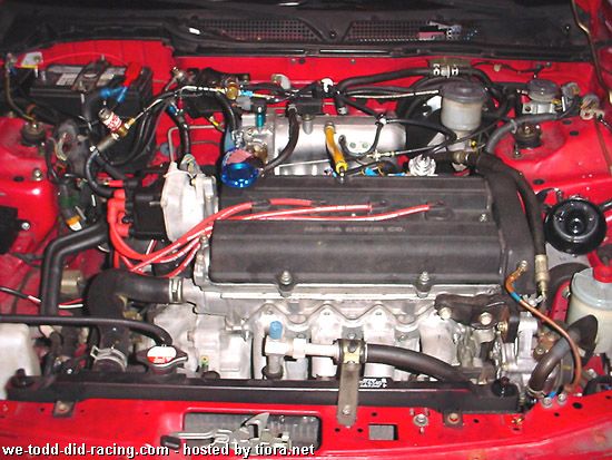
| MaXReV-BoT Anmeldedatum: 10.09.2004 Beiträge: 2896 Wohnort: World-Wide-Web | zitieren *** ÜBERSETZUNG IN DEUTSCH FOLGT *** Here is a little guide I threw together quickly with some old pictures I had laying around from when my friend decided to turbo his 3rd gen Integra. Most of us are pretty familiar with these basics so this is intended for people who are newer to turbo.... enjoy. DRAG Generation 3 install on 3rd gen Integra Parts List: • Turbonetics T04/T3 Turbocharger • 4 into 1 Cast Iron Turbo Exhaust Manifold • Turbonetics Deltagate Mark II Wastegate • High Pressure/High Volume Inline Fuel Pump • Vortech 12:1 Boost Dependent FMU • Intake Air Filter Assembly • 27" x 7" x 2.5" Front Mount Intercooler • Mandrel-Bent Chrome-Plated Piping • HKS Super Sequential Blow-Off Valve • 2.5" Exhaust Down Pipe • Wastegate Dump Tube • Map Sensor Bypass Valves • Stainless Steel Braided Oil Feed Line w/ Fittings • Blue Silicone Couplers and Clamps • Oil Return Line Assembly • All Hardware and Fittings • All Gaskets • All Hoses and Hose Clamps I Inline Fuel Pump and FMU Installation 1) Preliminary
 2) Inline Fuel Pump Install a) In-tank or Inline Fuel Pump? Drag uses an Inline fuel pump which can provide the high pressure fuel delivery well suited for a FMU setup such as this. A high volume in-tank fuel pump such as a Walbro 255 In-tank fuel pump works better with larger injectors and a standalone. A 12:1 FMU will add 12 psi fuel pressure for every 1 psi of boost. If you had a static fuel pressure is set at 42 psi then at 7 psi the FMU will raise your fuel pressure to 126 psi! The Walbro Fuel pump was meant to provide high volume but cannot provide pressures this high. b) Cut the rubber fuel Line about 1.5 inches away from the fuel filter. Since you have to relief the fuel pressure it is a good time to replace your fuel filter as well and install a fuel pressure gauge or fuel pressure sender unit(If you decide on an electronic gauge). YouÂ’re going to want to get the pressure recording after the inline fuel pump if installing a gauge so you can get an accurate reading. 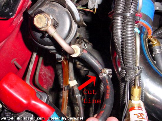 c) Connect brass fittings as shown to the inline fuel pump. 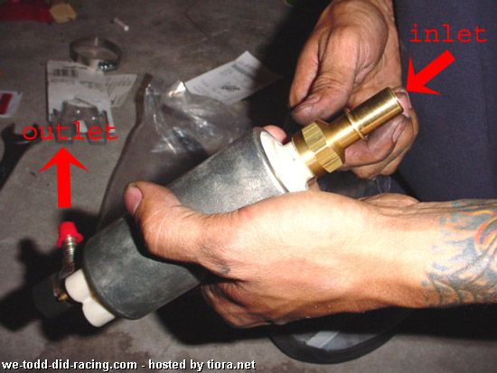 d) Connect the Fuel Pump inlet to the rubber hose coming off the fuel filter. Connect the Outlet to the Rubber hose going to your fuel rail. Make sure to use gator clamps to secure the hoses. Remember the outlet make a 90 degree turn and is on the side with the power terminals. 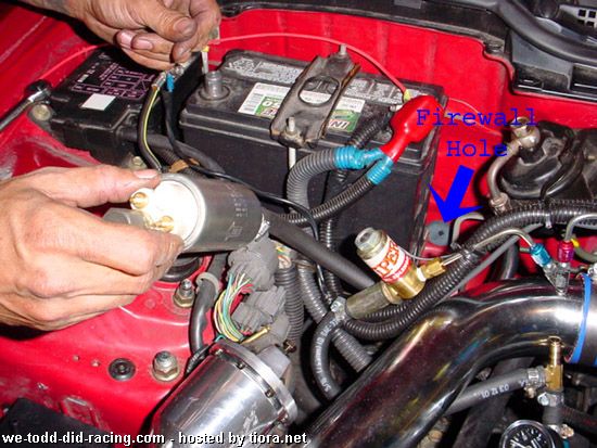 e) Secure the fuel pump to the air conditioning hard lines with supplied hose clamp. 3) Electrical connections for Inline Fuel Pump
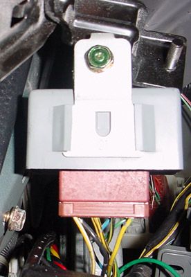 d) Disconnect the brown connector from the grey relay box locate pin # 4. 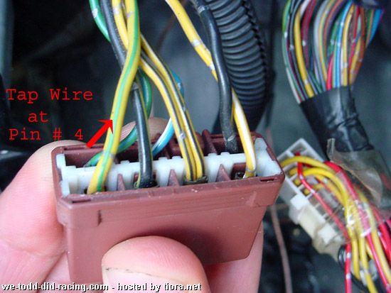 e) Pin # 4 should connect to a yellow wire with a green stripe. Tap this wire with a T-Tap or splice and solder the 14 gauge wire here to provide power to the fuel pump. f) A better way to do this is to run a relay inline so one does not leach the current on the existing wire. This can be accomplished by purchasing a relay as shown an connecting the wires as described: 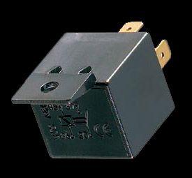 Pin 86- Pin # 4 wire on Main relay Pin 85- chassis ground inside the car Pin 87- Positive terminal on inline fuel pump Pin 30- Positive on your cars battery 4) Testing the Fuel Pump a)Reconnect negative terminal on battery b)Turn key to position # 2 – allows use of power but does not crank the engine over. c)Check for any fuel leak d)Repeat process 3 times e)When the key is turned to position two the inline fuel pump should turn on for a second and turn off. If it continues to run then you tapped the wrong wire on the main relay. 5) FMU “boost dependent regulator” installation
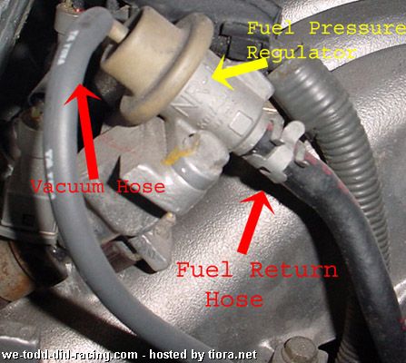 d) Connect Fuel hose return hose to Fuel exit on the bottom of the FMU.  e) Connect a Fuel Line from the Fuel In connection on the side of the FMU to the open fitting on the Fuel pressure regulator where the fuel exit used to be. f) Cut the Vacuum hose connected to the top of the fuel pressure regulator 2-3 inches away and plumb in a vacuum hose T and run a vacuum line to the Vacuum source on the FMU. g) Reconnect battery, start car, check for fuel leaks. Remove ground again after completed. II Exhaust Manifold Removal 1) Radiator removal a) Drain the radiator fluid. Remove coolant overflow hose and upper and lower radiator hoses.  b) Disconnect all connections for both fans. 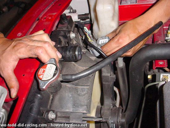 c) Remove Fans and radiator. 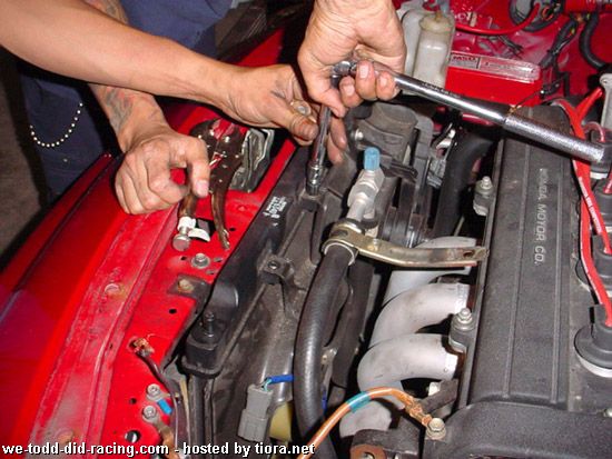  2) Exhaust Manifold Removal a) Jack the car up and rest on 2 Jack stands. Remove the stock heat shield and proceed to remove 9 nuts connecting your manifold to the head. Shown here is the removal of a DC 4-1 Header. 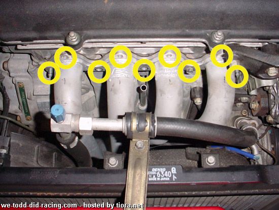 b) Remove the bolts from the catalytic converter and the support bracket. 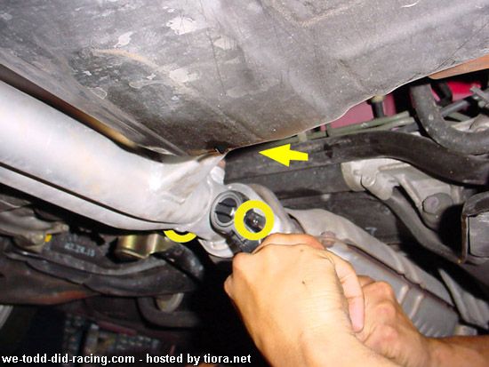 c) Remove the exhaust manifold and drop from below.  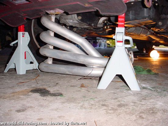 3) Cutting Clearance on the Block a) Cut or File the webbing on the block approximately ½ inch to make room for the turbo compressor housing.   III Oil Return and Feed Lines 1) Oil Pan Removal a) Drain Oil. Remove front and rear engine stiffners.  b) Remove clutch cover(to expose all oil pan nuts + bolts).  c) Remove all oil pan nuts and bolts.  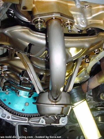 2) Drilling and Welding the Oil Pan. a) With the removed oil pan drill an appropriate size hole in the location shown. Note: the position must be high enough so the returned oil is above the oil sitting in the oil pan when car is running.  b) Completely clean the oil pan to remove any metal shavings and oil. c) Weld the supplied L-shaped pipe included for the oil drain in the hole drilled. This can be done either with JB weld or professionally welded (highly recommended). d) Re-install Oil Pan, new oil filter, and screw in oil pan bolt. 3) Oil feed fitting
 c) Attach the OEM oil pressure sender. d) Connect the supplied brass AN fitting to the remaining hole using Teflon tape. e) Attach the steel braided line included to this AN fitting (Do not use Teflon Tape). f) Route the Braided line across the top of the transmission housing towards the front of the car. IV Turbo 1) Turbonetics T3-T04 Turbo a) The compressor housing on top and Turbine housing on bottom. Notice this turbo used has an older ford style 5 bolt exhaust housing. The 5 Bolt exhaust housings aren’t as efficient as Garrets newer 4 bolt exhaust housings which have a more efficient tangential flow path. Most turbo manifolds for sport compacts work better with a 5 bolt turbine housing because the housings have less of an offset and fit better in tight locations. 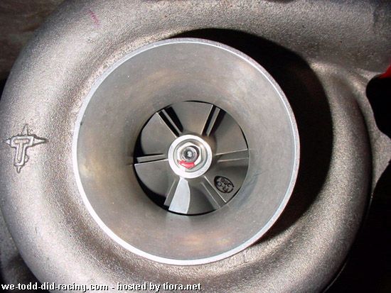  Here is the typical list of the Turbo specs for each engine provided by Drag: B18: T04E/T3 54 STAGE 3 .63 AR B16: T04B/T3 SUPER V-72 .63 AR D16: T04B/T3 SUPER V-72 .63 AR D15: T04B/T3 SUPER V-72 .63 AR H22: T04B/T3 SUPER V STAGE 3 .63 AR H23: T04B/T3 SUPER V STAGE 3 .63 AR F22: T04B/T3 SUPER V STAGE 3 .63 AR F23: T04B/T3 SUPER V STAGE 3 .63 AR 2) Attaching the oil feed and return fittings a) Install the oil return line flange and connect the rubber hose as provided. 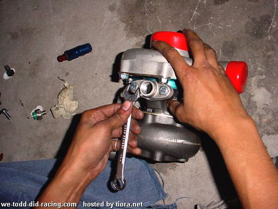  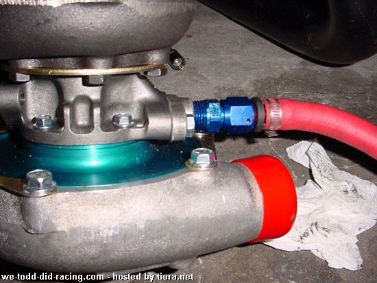 b) Install the copper oil feed fitting. 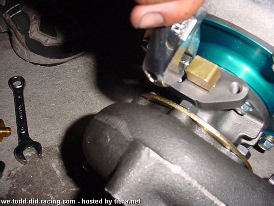 3) Clocking the Turbo and attaching fittings a) Turn or “clock” the compressor housing so that the compressor outlet faces down. And clock the Turbine housing so the oil drain line will face downward and the oil feed line faces upward. This can be done by loosening the 6 bolts on either the compressor housing shown with the yellow arrow or the 6 bolts on the turbine side shown with the red arrow. You may need a bench vice and rubber mallet/pry bar to turn the turbine side once the bolts are loosened. 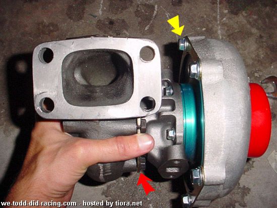 b) Tighten the bolts snugly. 4) Connect the turbine flange to the Turbo manifold  5) Attach the now constructed turbo and manifold onto the head from underneath the car and lightly tighten 2 nuts to hold the manifold in place.  6) Down pipe a) The Drag 3 kit comes with both a 2.5” down pipe and a wastegate dump tube. For this application we elected to weld the dump tube into the down pipe for noise reduction and emission purposes. If you choose to do this make sure you weld the dump tube gradually into the down pipe at least 18 inches downstream. This welding location shown here is not perfect and could have been done better. 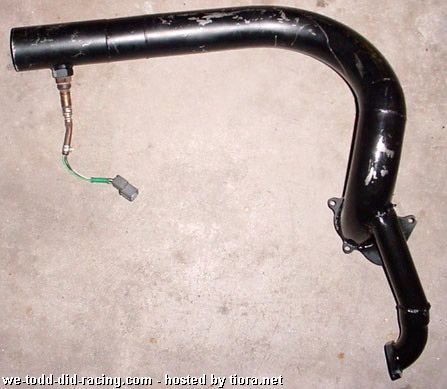 b) Install the down pipe to the 5 bolt exhaust housing. Note: You are going to have to drive your car to a local welder with an open down pipe and have him weld a flange to connect to your catalytic converter. Have fun scaring your neighbors and avoiding the police ") . It’s a good time to have him install a high flow cat and install a larger diameter exhaust. Or you could be smart and spend 5 dollars on some cheap flex pipe sold in any auto parts store and use flanges to temporarily connect the down pipe to your exhaust. . It’s a good time to have him install a high flow cat and install a larger diameter exhaust. Or you could be smart and spend 5 dollars on some cheap flex pipe sold in any auto parts store and use flanges to temporarily connect the down pipe to your exhaust.  c) Finish bolting the manifold to the Head. 7) Connecting Oil feed and return Lines a) Connect the oil feed line to the turbo. Notice it is facing upwards. 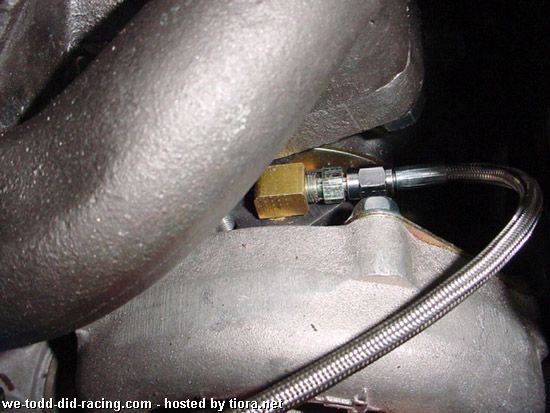 b) This kit comes with shiny insulating wrap which Should wrap around the oil return line to keep it from melting near the down pipe. Attach the Oil return line to the welded fitting in the oil pan. Make sure the line does not touch the down pipe and has a short direct route to the oil pan free from any kinks. This is extremely important because the oil return line is gravity fed. 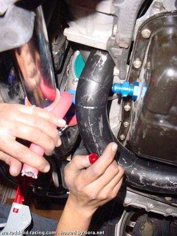 V Wastegate 1) Turbonetics Deltagate Mark II Wastegate a) These wastegates tend to cause boost creep(spikes and fluctuations in regulating the PSI) and I highly recommend upgrading to a Tial 35 mm or 38 mm down the road to prevent this.  b) Install the Wategate. Note: As you can see the wastegate is mounted on cylinder 1 runner alone. When looking for a good turbo manifold a better placement of the wastegate would be located where all the runners converge in the manifolds collector. These manifolds tend to cause boost creep, especially if you free up a lot of back pressure in your exhaust. 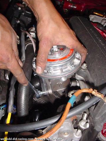 c) Connect the Brass Fittings on the wastegate.  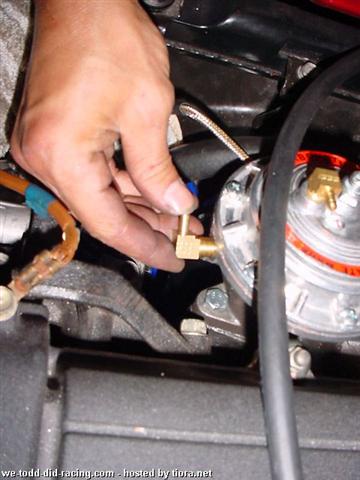 2) Connect the Vacuum lines to the waste gate. a) The top port(red arrow) connects to an electronic boost controller, if you don’t have one then leave it open. The side port (yellow arrow) connects to a vacuum source. You have 2 options: 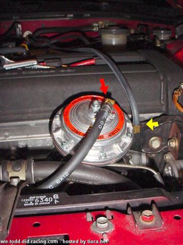 b) Connect the vacuum line to the port on the compressor housing. Pro- This will allow the wastegate to more consistently control the response and ability to control boost pressure. In turn this will help deter boost spikes or quick heat soak problems with your intercooler. Con- Since there is a 1-3 PSI pressure drop through the intercooler piping and intercooler the wastegate will start to crack earlier and your torque curve will suffer because you will never reach basic boost setting on the wastegate. c) Connect the vacuum line to the intake manifold or a line connected to the intake manifold. Pro- This will allow slightly better turbo response because it will allow the turbo to boost all it wants until the pressure reaches the intake manifold. Con – It will allow for more brief spikes in boost which will cause the intercooler to be hit with a blast of higher temperature. d) If connecting to the Intake manifold it is best to tap the brake booster line to connect the wastegate. Make sure you tap the brake booster line(red arrow) before the check valve(yellow arrow) as shown. 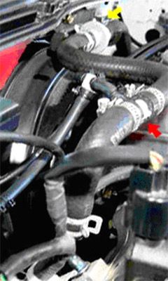 e) Another solution is to use a Vacuum box connected to the brake booster so you can connect a wastegate, blowoff valve, boost gauge, Fuel pressure Regulator, Map Sensor, ect. Mcmaster Carr makes an inexpensive one and Golden Eagle sells a more expensive one. 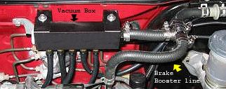 VI Intercooler and Piping 1)Intercooler mounting 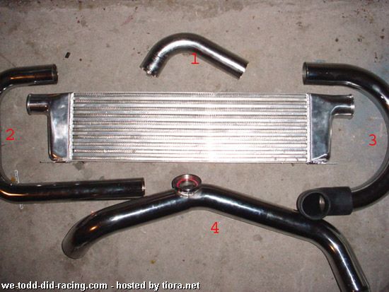 a) Remove the front bumper.  b)Align the intercooler on the Bumper support make sure it as close to the radiator as possible so the backside is flush with the back of the bumper support. Mark the holes proceed to drill. 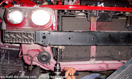 c) Screw the Intercooler to the bumper support.  2) Intercooler Pipe Connections a)Connect the 90 degree elbow #1 to the Compressor Exit using silicon hose connectors and clamps. Use a silicone based lubricant or some soap to lubricate the inside of rubber couplers if needed to aid in squeezing onto the intercooler pipe. A petroleum based lubricant could dry and crack the rubber later on. b) Connect the driver side 180 degree bend #2 to pipe #1 and intercooler. A hole must be cut in the driver side splash guard to feed the intercooler pipe through.  c) Connect the passenger side 180 degree bend # 3 to the exit of the intercooler. 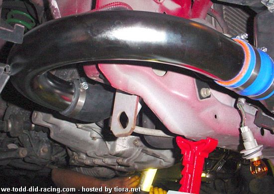 d) Connect a 90 degree rubber coupling to pipe # 3 to upper charge pipe # 4.  e) Connect the Upper Charge Pipe # 4 to the throttle body. 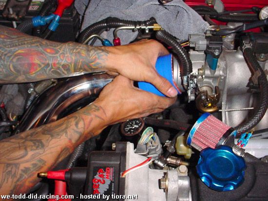 f) Reinstall the bumper and splash guards. g) Newer versions of this kit should come with a 2 more pipes. Connect the Turbo inlet adapter pipe to the turbo inlet and the Intake pipe to the adapter pipe using silicone hose. Attach the provided K+N Filter to the end of the intake pipe.  VII Blow off Valve 1) The blow off valve is attached to the upper charge pipe with a snap ring tool provided to install the HKS Sequential blow off valve.  a) Use the supplied vacuum hose to connect the Blow off valve with a vacuum source after the throttle body. Either the Intake Manifold, Brake Booster line, or a Vacuum box are all fine. If the Blow off valve fails to open or you hear compressor surge then it is possible that the vacuum source isnÂ’t strong enough to open the blow off valve. Try using a vacuum source which isnÂ’t taped with too many other connections.  b) You can see from the above picture there is an adjustment screw so you can adjust the valve. If you are loosing boost under hard acceleration then tighten it because it is leaking. You can loosen it if the valve is too tight and is causing compressor surge.  c) Install the supplied little filter inline between the Blow off valve and vacuum source. This will keep contaminants from entering the blow off valve. 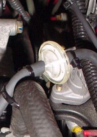 VIII Check Valves 1)Check valves are used to trick the factory ecu into not seeing any boost pressure. Honda never intended you to turbo your Integra and if the MAP sensor detects any boost it will throw a CEL code. A Map bypass uses check valves(one way valves) to bleed off boost before it reaches the stock map sensor. Check valves allow for boost pressure to be released when your intake manifold is pressurized and still keep any contaminants from being inhaled when your intake manifold is out of boost and is in vacuum like normal. 2) Map Sensor a) Remove the factory map sensor which is located on top of the throttle body by removing 2 screws. 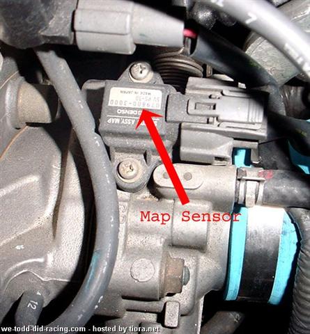 b) Replace OEM MAP Sensor with 90 degree fitting from included check valve assembly. Connect OEM Map Sensor to other end of assembly and secure harness down with zip ties. 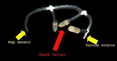 c) Here is the Basic Layout of a Check Valve. Its simply vacuum line teeÂ’d with check valves inline. If you were to build a MAP bypass yourself you can purchase check valves(or one way valves) from NAPA - Echlin part # 2-970.  d) Another option to use instead of check valves is a product called “Missing Link” It can be purchased for approximately 70 dollars and will make clean up your engine bay and simplify your setup. A Missing Link check valve has a built in check valve and sits between the MAP sensor and throttle body. They need to be cleaned every so often because they sometimes get dirty and clog. IX Preparing to Start the engine
4) Gap Spark Plugs to .030- NGK part # BCPR7ES-11 are preferred. 5) Remove the coil wire or Pgmfi fuse to prevent spark when priming the turbo. 6) Place oil feed line in a bucket (end which is normally connected to turbo) while other end remains connected to the engine. Crank the engine 10 times with 10 second pauses in between each attempt to fill about a quart of oil in the bucket. Now that the Oil feed line has been purged connect it to the turbo. Once connected crank the engine over 5 times to prime the turbo. 7) Reconnect coil wire or fuse. 8) Recheck all vacuum, fuel, coolant, wire connections. X Testing
4) Set ignition timing to factory and make sure no aftermarket chips which advance the timing are used. 5) Slowly drive the car with part throttle and pay close attention to any unusual sounds besides the fuel pump buzz and the blow off valve during shifting. 6) Shift into third and slowly rev up to redline listening carefully for any pinging or detonation. Immediately pull over if heard and check the Fuel system is functioning properly and the ignition timing is correct. If pinging persists then use colder spark plugs(# BCPR7ES-11) or retard the timing up to 5 degrees. If all is fine then shift into 4th gear and repeat. 7) If check engine light comes on then bypass service connector with paper clip and check engine code in factory service manual to troubleshoot. 8) If check engine light comes on when in boost only then check Map sensor bypass. 9) If engine misfires at high RPM check spark plug gaps. 10) If your car can’t build any boost pressure then check for leaks in the Intercooler piping, Intake manifold, exhaust leaks on wastegate, turbo manifold, and downpipe. 11) Never exceed 10 psi boost pressure. If this occurs check vacuum lines on wastegate. 12) Before turning off ignition let car idle for 20 seconds. © All rights reserved by Matthew Kirsch |
| ▲ | pn |
| Beobachter Anmeldedatum: 25.04.2005 Beiträge: 3 Wohnort: Hainburg | zitieren Hy wollte wissen ob man auch einen turbo in einen integra einbauen kann ohne das getriebe und kupplung verstärken müssen? |
| ▲ | pn |
| Beobachter Name: wachtel Fahrzeug: honda civic Anmeldedatum: 18.09.2005 Beiträge: 1 Wohnort: bremen | zitieren Hallo! können sie mich helfen , ich will in meine civic turbo instalieren(b16a) ,können sie sagen was müss ich kaufen und velche ECU . |
| ▲ | pn email |
| Trainee Anmeldedatum: 21.08.2005 Beiträge: 34 Wohnort: Düsseldorf | zitieren holy...hat das jemand schonmal nachgebaut?  |
| ▲ | pn yim |
Elite  Geschlecht: Anmeldedatum: 31.07.2006 Beiträge: 1635 Wohnort: SK | zitieren ja sowas wäre nicht schlech |
| ▲ | pn |
| Grand Master Anmeldedatum: 03.08.2005 Beiträge: 12845 Wohnort: Mandschouku | zitieren hallöchen. super anleitung. wie stehts mit der versprochenen übersetzung? ") |
| ▲ | pn email |
| Senior Name: Rufname Hossa ;-) Geschlecht: Fahrzeug: EE8 ; ED6 ; EE4 4WD Anmeldedatum: 04.12.2007 Beiträge: 421 Wohnort: Elbflorenz | zitieren Übersetztung?????????????? |
| ▲ | pn |
General  Name: tim Geschlecht: Anmeldedatum: 14.11.2005 Beiträge: 3863 Wohnort: reichshof nrw | zitieren habt ihr mal auf das datum geschaut? |
| ▲ | pn |
Premium-Member   Name: Sören Geschlecht: Fahrzeug: Honda Accord Modell: CM2 Executive Motor: 2,4l 190PS Anmeldedatum: 17.07.2005 Beiträge: 2903 Wohnort: München Heimat : Dresden | zitieren Ist doch egal oder ?!?! Vielleicht findet sich ja noch jemand der es übersetzen will  |
| ▲ | pn |
| Gast | zitieren Mach mit!Wenn Dir die Beiträge zum Thread "Complete Guide for Drag 3 Turbo Installation" gefallen haben oder Du noch Fragen hast oder Ergänzungen machen möchtest, solltest Du Dich gleich bei uns anmelden:Registrierte Mitglieder genießen die folgenden Vorteile: ✔ kostenlose Mitgliedschaft ✔ keine Werbung ✔ direkter Austausch mit Gleichgesinnten ✔ neue Fragen stellen oder Diskussionen starten ✔ schnelle Hilfe bei Problemen ✔ Bilder und Videos hochladen ✔ und vieles mehr... |
| ▲ | |
| Ähnliche Beiträge | Re: √ | Letzter Beitrag | |
|---|---|---|---|
 Civic Turbo Drag Civic Turbo DragWusste nicht genau wohin mit dem Video aber ich machs einfach mal hier rein.
Ich finde das Video ziemlich beeindruckend aber ich verstehs nicht so ganz :).
Der hat weniger als 350Ps, das volle Interior drinne und nen Coupe(Der ja etwas mehr wiegen... [Turbo]von Sum41 | 1 792 | 15.04.2009, 20:07 XtremeCar | |
| Eg6 Turbo Drag Tool Moin
Wollte endlich mal meine Eg6 Turbo vorstellen.Habe ihn im November 2017 gekauft. Bei mir wird er für den Drag Einsatz
Komplett umgebaut.
Paar Daten zum Eg6
- B16a2 laut Besitzer 320ps
- Kompletter MKR Umbau
- Oz Felgen 17zoll
- 8Kolben Bremse Vorne... Seite 2 [Civic 92-95]von Acura_Rsx_Turbo | 13 1.064 | 02.03.2018, 12:43 Acura_Rsx_Turbo | |
| the never ending Story =) *Complete* Bilder S. 8+9 Mein del sol fürn Sommer ...
Ist gerade beim Lackierer und bekommt nen Roten Candy lack mit pearl effect ...
Weitere Teile die gekauft sind
LSD Doors
ITB
Tss Fächer
Xenon
etc. ... Bilder und teile folgen... Seite 2, 3, 4, ... 8, 9, 10 [Del Sol]von Shupatino | 93 5.956 | 19.05.2010, 18:57 holliwood | |
| Car & Style - Bilder *update* -> nun complete !!! So Jungs,
wie versprochen habe ich die Bilder hochgeladen vom Car & Style 2009 in Hamburg. Zwar noch immer nich alle, weil ich anscheinend einfach zuviele Bilder geschossen habe *g* irgendwas mit über 500... [Japan Projects]von Zukuu | 2 676 | 05.10.2009, 18:28 Zukuu | |
| Installation Hallo...,
bei der Installation bekomme ich gleich die folgende Meldung
MediaWiki 1.15.4 Installation
Can't write config file, aborting
In order to configure the wiki you have to make the config subdirectory writable by the web server. Once... von lombo99 | 1 316 | 26.06.2010, 06:07 lombo99 | |
| Hilfe bei der Installation Hallo zusammen,
wollte soeben mir ein intereres Wiki erstellen und sitze Momentan an folgenden Punkt fest.
Das Tutorial:
http://www.youtube.com/watch?v=NR0oYlVjXxQ&feature=player_embedded
Video abspielen
Zeit: ab 05:02min
Dieser Link den er auf der... von voov | 4 242 | 27.09.2012, 12:59 voov | |
| Installation von twiki Hi,
ich würde gerne twiki installieren, komme allerdings mit den diversen Installguides nicht zurecht...
siehe:
http://twiki.org/cgi-bin/view/TWiki/TWikiInstallationGuide#Preparing_to_install_TWiki
Gigt es auch eine einfachere Möglichkeit twiki zu... von jan.hellmann | 0 541 | 05.07.2011, 15:02 jan.hellmann | |
| Installation und konfiguration Hi und zwar habe ich mir über Oracle das jdk 8 herunter geladen und auf meinem Desktop installiert. Ich habe mir die IDE intellij herunter geladen.
Ich habe ein Projekt erstellt und wollte durch die Startmethode
public static void... von NewProgrammer | 0 357 | 17.11.2020, 17:26 NewProgrammer | |
| Hilfe bei Installation Hallo zusammen,
ich möchte gern mal phpwiki ausprobieren. Habe alles auf meinem Webserver geladen und die config.ini angelegt. Wenn ich jetzt das wiki aufrufe, dann kommt folgene Meldung: lib/FileFinder.php:187 Error: /tmp: file... von Ludwig | 2 164 | 11.10.2013, 10:33 Ludwig | |
| Fehler bei der Installation? Ich weis nicht ob das hier rein gehört, aber es hat was mit PHP bei der Installation zu tun:
Ich habe mediawiki auf dem Server installiert. Alles lief super bis dann aber folgende Fehlermeldung (oben) kam:
Warning: ini_set() has been disabled for... von denka | 3 1.122 | 19.02.2008, 13:53 mgutt | |
© 2004 - 2026 www.maxrev.de | Communities | Impressum |